


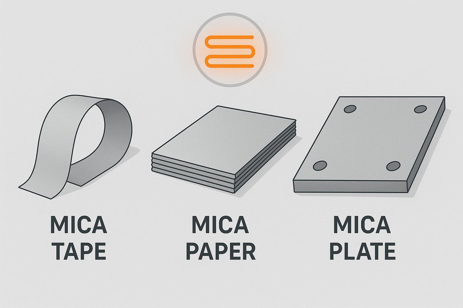
When you’re insulating right next to a heating element, the choice of mica form has real consequences for safety, reliability, and manufacturability. Rigid boards that can be drilled and mounted behave very differently from thin wraps that conform around leads and coils. And while mica minerals themselves can tolerate extreme heat, the usable continuous temperature of a composite (plate or tape) is usually limited by its binder system. Think of it this way: mica is the brick; the binder is the mortar.
This guide compares mica paper, rigid mica plate (laminates), and mica tape specifically for heater‑adjacent electrical insulation. We’ll use conservative, auditable ranges, call out the standards that govern testing, and organize recommendations by scenario rather than declare a single winner.
Quick comparison — mica paper vs mica plate vs mica tape
Below is a neutral snapshot of typical capability bands and best‑fit scenarios. Values are indicative and depend on exact grade, thickness, and binder/reinforcement. Verify against current datasheets and standards.
| Product form | Typical thickness range | Continuous temperature (conservative) | Short‑term peak temperature | Typical dielectric strength (room temp) | Mechanical format | Best for (heater context) |
|---|---|---|---|---|---|---|
| Mica plate (rigid laminate) | ~0.3–20 mm | Muscovite plates ~500–600 °C; Phlogopite plates ~700–800 °C (binder‑dependent) | ~1000–1100+ °C per grade | ~15–30 kV/mm (grade/conditioning) | Rigid, machinable, screw‑mountable | Supports, barriers, fixtures near elements; slot liners; thin rigid shields |
| Mica tape (glass/film reinforced) | ~0.08–0.20 mm per layer (common) | Often limited by system class (F/H ≈155–180 °C in motors/coils due to binders) | Material layer survives ~850–1000+ °C; cable fire tests at ≥830 °C (IEC 60331) | ~20–25 kV/mm at mica layer (high‑grade) | Flexible wrap; slit widths ~10–50 mm | Wrapping leads/terminations; compact coil turns; fire barrier layers in harnesses/cables |
| Mica paper (base layer) | ~0.05–0.15 mm per layer (typical) | Depends on composite; standalone durability limited without reinforcement | Similar to plate/tape when laminated; mineral peaks depend on muscovite vs phlogopite | Aligns with plate/tape when part of laminates/tapes | Thin sheets used to build laminates/tubes/gaskets | Intermediate layers in custom composites; thin gap insulation where reinforced |
Evidence notes:
- Rigid mica plate bands and flexural/mechanical context are supported by manufacturers such as Elmelin and Axim; dielectric values are typically reported per IEC 60243/ASTM D149. See Axim’s sheet overviews and Elmelin’s product page for ranges as of 2025. Axim product overview • Elmelin mica sheet
- Cable fire integrity with mica tape (≥830 °C, 90–120 min) is documented in IEC 60331 and manufacturer catalogs (e.g., Prysmian). As of 2024, IEC 60331‑4 includes an optional 1000 °C severity. IEC 60331‑4:2024 summary • Prysmian marine/offshore catalog
Rigid mica plate (laminate): the go‑to near hot elements
Rigid mica plates combine high dielectric strength with dimensional stability and machinability, which makes them the default choice for heater supports, barriers, and fixtures.
Specs
- Typical thickness: ~0.3–20 mm, with specialty grades outside this band.
- Dielectric strength: approximately 15–30 kV/mm at room temperature depending on grade and conditioning (IEC 60243 / ASTM D149).
- Mechanical: Flexural strength commonly ≥80 MPa on many industrial grades; good screw retention and edge stability.
- Thermal window: Practical continuous ranges are governed by the binder and mineral type—muscovite composites often ~500–600 °C; phlogopite composites ~700–800 °C; short peaks around ~1000–1100+ °C, per manufacturer grades and test conditions.
Pros
- Machinable for brackets, slots, and precision fixtures.
- Stable creepage/clearance distances under heat.
- Often carries UL 94 V‑0 flammability rating in appropriate constructions.
Cons
- Heavier and thicker than tape; can add stack height.
- Binder choices determine continuous service limits; wrong resin can prematurely degrade.
Who it’s for
Toasters, ovens, band/strip heater mounts, furnace fixtures, and screw‑mounted thin rigid shields adjacent to elements.
Constraints
- Verify the binder system (silicone/inorganic for higher‑T; epoxy/phenolic for lower‑T use) against your hot‑zone profile.
- Room‑temperature dielectric data may not translate linearly at elevated temperatures—test at operating conditions.
Evidence
Yuefeng Mica’s product page lists mica boards with thickness 0.3–20 mm, flexural ≥80 MPa, UL 94 V‑0, and temperature scope by binder/mineral type. See the page for construction examples and applications. Yuefeng mica board product page
External manufacturers corroborate the rigid‑plate role and capability bands for heater‑adjacent use as of 2025. Axim overview • Elmelin product page
Mica tape for wraps, terminations, and cable fire barriers
Mica tape is a thin, flexible composite made from mica paper plus a reinforcement (glass cloth/veil or film) and a low‑organic binder. It excels when you need conformal coverage with high dielectric strength and, in cable systems, a proven fire barrier.
Specs
- Typical overall thickness: ~0.08–0.20 mm per layer for common grades; thinner/higher grades exist.
- Widths: Common slits ~10–50 mm for cable and harness applications.
- Dielectric strength: often ~20–25 kV/mm at the mica layer (IEC 60243 / ASTM D149), depending on construction.
- Fire‑survival: In correctly designed cables, mica tape layers help pass IEC 60331 (≥830 °C, 90–120 min); BS 6387 categories (C/W/Z) are widely cited in UK applications.
Pros
- Conforms around leads, terminations, and compact coils.
- Enables thin‑build lap coverage tuned to voltage and fire‑test needs.
Cons
- Continuous electrical service in motors/coils is often limited by the overall insulation system’s thermal class (F/H ≈155–180 °C) rather than mica itself.
- Requires controlled wrapping practice (tension, overlap) to ensure dielectric and fire performance.
Who it’s for
Lead/terminal wraps near hot zones, compact turn insulation, and fire‑barrier layers in wiring harnesses and cables routed close to heaters.
Constraints
- Confirm layer counts and overlap for your voltage and test standard; use qualified cable designs for IEC 60331/BS 6387 performance.
- Elevated‑temperature dielectric behavior depends on the reinforcement and binder; test in the intended environment.
Evidence
IEC 60331‑4:2024 includes an optional 1000 °C severity and codifies ≥830 °C test regimes; cable makers document mica‑tape layers as the circuit‑integrity barrier. IEC 60331‑4:2024 summary • Prysmian marine/offshore catalog
Mica paper for building custom composites around heaters
Mica paper is the foundational layer from which tapes and laminates are made. As a standalone component in hot zones it’s mechanically fragile, but it’s invaluable for building thin, tailored composites (laminates, tubes, gaskets) that need mica’s dielectric strength and thermal stability.
Specs
- Typical layer thickness: ~0.05–0.15 mm; heavier layers exist for laminates.
- Dielectric strength: aligns with tape/plate values when part of a composite (10–25+ kV/mm depending on construction and thickness).
- Thermal behavior: governed by mineral choice (muscovite vs phlogopite) and the binder system used in the composite.
Pros
- Enables highly customized multi‑layer builds with precise thickness control.
- Good for thin gaps where rigid laminates are too bulky, once reinforced.
Cons
- Poor durability as a standalone layer near elements without reinforcement.
- Binder and lamination quality control become critical to performance.
Who it’s for
Engineers building bespoke laminates, tubes, and gaskets for heater assemblies; OEMs needing specific thickness stacks and geometries.
Constraints
- Use reinforcement (glass/film) or lamination to achieve mechanical robustness.
- Validate dielectric and thermal limits on the finished composite, not just the paper.
Evidence
Industry catalogs align on the role and dimensions of mica paper as the base for tapes/laminates; dielectric performance follows composite design and test standards (IEC 60243 / ASTM D149).
How to choose for heating elements: a scenario‑based decision map
Here’s the deal: start with your hot‑zone profile, mounting method, and voltage class. Then select the mica form that fits the mechanical format and test obligations.
- Rigid mounting near elements (brackets, barriers, screw‑mounted shields): Choose phlogopite‑based mica plates with silicone/inorganic binders for ~700–800 °C continuous environments, allowing short peaks per datasheet. Use muscovite‑based plates closer to ~500–600 °C continuous. Maintain creepage/clearance distances and confirm UL 94 V‑0 where flammability control matters.
- Thin, conformal wraps around leads/terminations: Choose mica tape with appropriate thickness and overlap; for harnesses requiring circuit integrity under fire, design to IEC 60331 and, where applicable, BS 6387. Validate wrapping practice in situ.
- Compact coils or turn insulation near hot spots: Use mica tape grades specified for motor/transformer turns; remember the overall insulation system may be limited to Class F/H.
- Custom gaskets/tubes or thin laminates: Use mica paper as an intermediate layer but reinforce or laminate for mechanical strength; validate the finished composite against dielectric and thermal targets.
- Safety and reliability notes
- Derate continuous service temperature relative to datasheet peaks; aim for conservative bands and verify at operating temperature.
- Test dielectric strength at the expected operating temperature, not just at room temperature (IEC 60243 / ASTM D149 methods as applicable).
- Document lap coverage, overlap percentage, and tension for wraps; qualify process parameters like any critical insulation step.
Standards primer and what they mean for your design
- IEC 60371 (mica materials): Family of specifications many mica laminates reference on datasheets; use it to orient material classification and properties.
- IEC 60243 / ASTM D149 (dielectric breakdown): Common test methods for reporting kV/mm; most values are room‑temperature unless specified.
- IEC 60085 / IEC 60216 (thermal class and RTI): Frameworks for electrical insulation system classification; remember that organic binders set continuous service class limits even when mica is present.
- UL 94 (flammability): Many mica laminates qualify to V‑0; check your exact construction.
- IEC 60331 (fire‑resistant cables): Defines circuit‑integrity tests at ≥830 °C for 90–120 minutes; IEC 60331‑4:2024 adds an optional 1000 °C severity. IEC 60331‑4:2024 summary
- BS 6387 (C/W/Z): UK categories for fire, fire with water, and fire with mechanical shock; rely on manufacturer documentation for cable qualification details.
Also consider (supplier note and disclosure)
Disclosure: Yuefeng Mica is our product. For rigid heater supports and thin shields, Yuefeng’s mica boards list thicknesses of 0.3–20 mm, flexural strength ≥80 MPa, and UL 94 V‑0 on applicable grades, with temperature windows dependent on binder and mineral type. Visit the product page for construction details and machining options. Yuefeng mica board product page
For background on mineral selection—muscovite vs phlogopite—and how dielectric strength differs (e.g., muscovite ~15–20 kV/mm; phlogopite ~10–15 kV/mm), see the technical explainer. Yuefeng blog: phlogopite vs muscovite sheets
Wrap‑up
Choose the mica form by the job it needs to do next to the heater: rigid plates when you need mounting and dimensional stability in hot zones; tape when you need thin, conformal dielectric and a fire barrier; paper when you’re building tailor‑made composites that will be reinforced. Anchor decisions in conservative continuous temperature bands, validate dielectric performance at elevated temperatures, and slot your design against the relevant standards and test regimes. Then verify everything against current datasheets before you lock the BOM.


